
PDLC玻璃生厂商福耀玻璃
PDLC调光玻璃
视频 http://www.fygi.com/uploads/19041075750.mp4
产品原理:
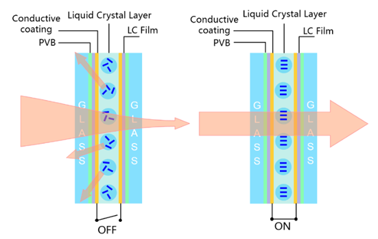
PDLC,中名叫聚合物分散液晶。无电场下,液晶分子会呈现不规则的散步状态,呈现透光而不透明的外观;施加电场时液晶分子呈现整齐排列,光线可以自由穿透,呈现透明状态。同时,由于这种断电时高散射特性,所以调光玻璃在断电时可作为投影屏使用。
主要优点:
• 个性调节玻璃透光度,提升用户体验
• 替代遮阳帘,提升车内空间
• 有效提升私密性,保护用户隐私
适用产品:夹层玻璃(天窗/侧窗/后挡)

从福耀京东方合作看汽车智能调光玻璃的新发展
2020年6 月 1 日,福耀集团与京东方集团举行战略签约仪式,双方将结合各自产业资源和技术优势,在汽车智能调光玻璃和车窗显示等领域进行战略合作,共同开拓市场,实现互利共赢[1]。此次双方的合作,将进一步推进智慧视窗产品在乘用车等更多领域应用。随着物联网、人工智能、大数据技术发展,双方还将共同拓展人车交互应用,在交通领域为全球用户带来高附加值的创新产品和解决方案。
福耀集团1987年成立于中国福州,是专注于玻璃生产的大型跨国集团, 1993年在上海证券交易所主板上市,2015年福耀集团在香港交易所上市[4]。到目前为止,福耀已为宾利、奔驰、宝马、奥迪、通用、丰田、大众、福特、克莱斯勒、日产、本田、现代、菲亚特、沃尔沃、路虎等世界知名品牌,以及中国各汽车厂商提供全球OEM配套和售后服务,汽车玻璃产品销量约占全球市场的25%[5],成为与旭硝子(日本)、板硝子(日本)、圣戈班(法国)、信义玻璃(中国香港)等著名汽车玻璃厂商齐名的汽车玻璃供应商[6]。
然而,即使作为汽车玻璃的龙头企业,福耀集团也面临如何实现产品更新换代、提升产品附加值的难题。高速计算、人工智能、5G网络等新技术为智能制造业带来了前所未有的机遇。福耀集团确立了以汽车玻璃为主业,充分利用新兴技术,发展上下游产业链的发展新方向。正是看准了调光玻璃的广阔应用前景,福耀集团积极研制调光玻璃,现已推出了调光玻璃、智能显示玻璃、抬头显示玻璃等多种智能型汽车玻璃技术产品。从福耀集团的专利申请看,他们从2012年开始申请智能调光玻璃相关专利,迄今为止,已经申请专利24项。我们结合专利来看一下福耀玻璃的黑科技。
从福耀京东方合作看汽车智能调光玻璃的新发展
图1 福耀集团的智能调光玻璃产品
福耀集团开发了多种调光材料,包括电控调光玻璃、光控调光玻璃和热致调光玻璃等调光膜材料。开发最多的产品是电控调光玻璃,通电控制玻璃内层可调光膜的状态,在透光和不透光间调节,具有极佳的隐私保障功能,无需安装遮阳帘。2018年,该技术已申请专利并获授权——CN108515752B ,一种无遮阳帘的天窗总成玻璃,包括外片玻璃和内片玻璃,所述外片玻璃和内片玻璃之间设有调光层。该无遮阳帘的天窗总成玻璃具有可见光透过率为8%~20%,可见光反射率不超过5%,太阳能直接透射比低于10%,同时太阳能总透过率低于20%的复合功能,并且制作成本合理,能够全面地替代机械式的遮阳系统,优化车内垂直空间,实现轻量化节能。
-
智能显示玻璃
从福耀京东方合作看汽车智能调光玻璃的新发展
图2 福耀集团的智能显示玻璃产品
福耀集团充分利用自身在电控玻璃技术方面的优势,结合越来越热的智能家居需求,将汽车打造成移动的家,使整车人员享受到驾乘乐趣。福耀集团推出的智能显示玻璃,可将文字、图案、充电比例、联系电话等信息显示在玻璃上;也可作为幕布,显示私人定制的信息,查看图像或影片。早在2015年,福耀就提出了"一种发光效果可调的车辆天窗总成"专利-CN105291789B,车辆天窗总成包括双层复合玻璃和固定在所述双层复合玻璃的侧边缘的线状光源,所述双层复合玻璃为中空玻璃或真空玻璃,所述双层复合玻璃自上向下依次包括上层玻璃、密闭腔室和下层玻璃,所述下层玻璃的上表面设有液晶调光膜。这种天窗具有多种图案显示状态,光线均匀柔和,同时还兼具调光、隔热、隐私保护等功能。之后,他们不断对该技术进行改进 ,2018年提出"一种带有弧形显示影院的汽车及观影方法"-CN201810043216.4,这种带有弧形显示影院的汽车适合在无人驾驶状态下进行观影,汽车天窗玻璃为调光玻璃,当两个投影装置向天窗玻璃上投影时,天窗玻璃能够由可见光透过率≥70%的状态转变成可见光透过率≤8%的状态。这种天窗显示玻璃不仅方便地形成实际观影效果好的弧形显示影院、保证合理的车内空间布置以及实现较好的显示播放效果,还能够实现无人驾驶状态下进行观影,使整车人员均能享受到驾乘乐趣。

 欢迎加入调光玻璃通讯录,目前比亚迪,光弈,极氪,福耀玻璃等已加入,可以筛选以下标签查看名录
主机厂 汽车配件 应用终端 材料 镀膜 玻璃 设备 变色材料 电致变色 调光薄膜 调光玻璃 PDLC 其他
欢迎加入调光玻璃通讯录,目前比亚迪,光弈,极氪,福耀玻璃等已加入,可以筛选以下标签查看名录
主机厂 汽车配件 应用终端 材料 镀膜 玻璃 设备 变色材料 电致变色 调光薄膜 调光玻璃 PDLC 其他